Going Mobile — install a station in your vehicle! (Part 1) continued…
Using a multimeter I checked the resistance between the mounting bolts and other portions of the truck. I had to extend the multimeter leads with wire in a couple of instances, and I had to make sure that I had a solid lead contact through painted and coated vehicle parts – the paint and coatings are often insulators. I was pleased to find very solid continuity, negligible resistance, from the mounting bolts to the truck body, to the frame, and even to the tailgate and bumper. I checked further continuity between the frame and elements of the suspension and exhaust system and discovered solid connectivity – not always a given condition even in modern automobiles. However, just because these various elements seemed to be electrically connected with low resistance to DC did not mean that the AC impedance at RF frequencies would be similarly nice and low for current flow. The multimeter continuity readings are a good indicator, but not the complete story for RF purposes. I would just have to give it a shot and see what kind of results I got in radio operations, and I might have to add some electrical bonding between vehicle components using broad, tinned copper braid if problems arose from poor ground continuity.
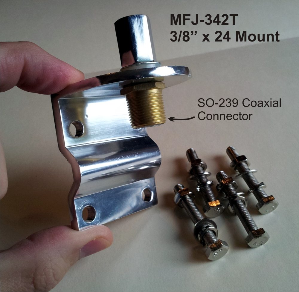
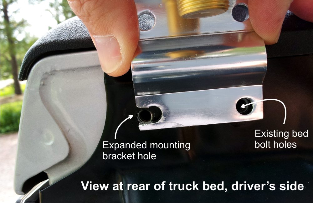
I purchased another MFJ product for the HF antenna mount: The MFJ-342T 3/8-24 Mirror/Pipe Mount. At about $25 it’s a pretty solid and inexpensive mounting option with the required female 3/8” x 24 threads on the top side and an SO-239 coaxial cable connector on the bottom. I dispensed with the smaller “back side” half of the 342T attachment bracket with the intent of using the pre-drilled holes in the main part of the 342T to simply bolt right onto the truck bed. However, my luck ran out – the spacing of the holes in the bracket did not quite match the spacing of the truck bed’s bolt holes. So, I went to the drill press and broadened one of the holes so that it extended to the truck bed’s hole spacing. A little drilling and cutting never hurt anybody… except for that guy who drilled through his hand and the other one who cut his finger off. Just be careful using power tools, please.
The 342T bracket then bolted onto the truck bed solidly, ready for a HF Stick to be screwed into the top side and coax cable on the bottom. Just to be sure, I rechecked the electrical continuity between the 342T bracket and the truck. Oh yeah… there’s that little matter of routing coaxial cables now.
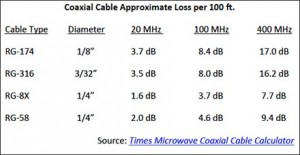
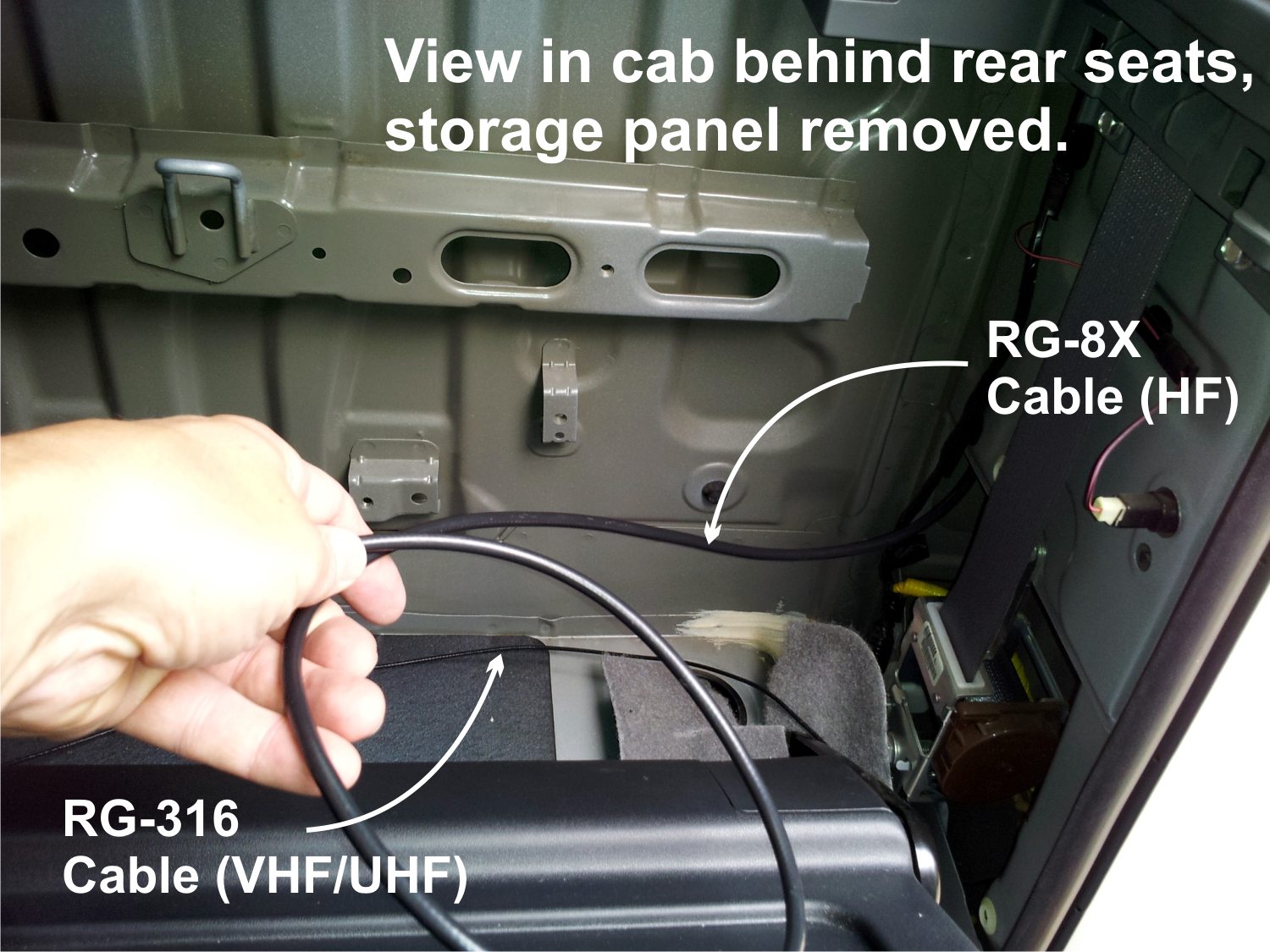
Coaxial Cables: The Diamond K412S antenna mount that I utilized for the VHF/UHF dual band antenna is sold with very narrow gauge coaxial cable (RG-316) attached and an SMA connector opposite the antenna end. The challenge, of course, was to get the cable routed from the antenna into the cabin to the transceiver chassis under the driver’s seat. Narrow gauge cables like this will exhibit relatively high signal loss per distance, but they are usually fine for the shorter runs associated with mobile installations.
Further, they can be readily routed through window or doors without crimping, taking advantage of their small diameter, flexibility and the door/window compressible seals. But, my preference was to try and avoid having any cables “hanging out” from doors or windows, mostly out of sight entirely, to meet that “low clutter” requirement. I’d have to seek another port into the cab or possibly drill one! (Oh, no! My beautiful truck! Perish the thought!)
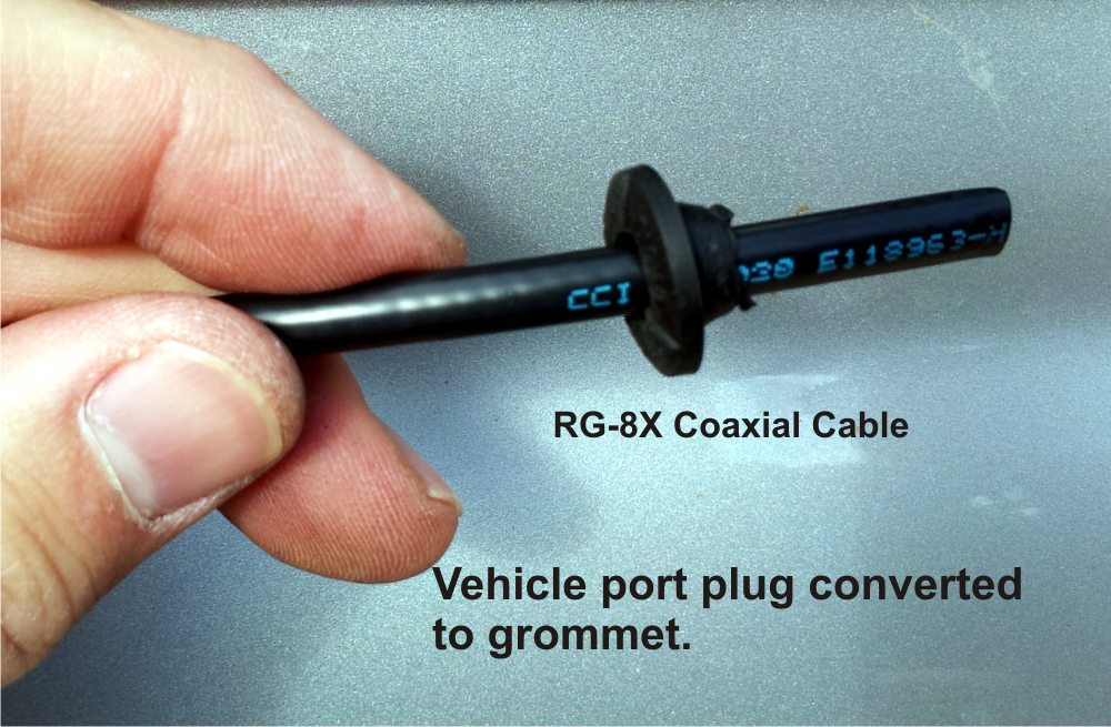
For the HF antenna coax I chose RG-8X, a 1/4-inch diameter cable with good low-loss characteristics that can easily handle the 100 watts of my barefoot station. However, it will not squeeze through doors or windows easily, so a port would definitely have to be discovered or created.
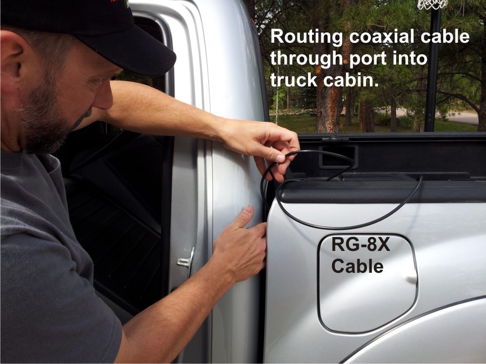
Of course, I planned ahead a little and had already discovered that the folks at Toyota are forward thinking and have accommodated us hams with several convenient ports into the newer Tacoma cabin. As it turned out, two rubber-plugged ports exist on both driver’s and passenger’s side at the rear of the cabin just below the top of the bed on the exterior and entering behind the rear passenger seats of the 4-door double cab. I could just reach the exterior port and plug by wedging my fingers into the space between cab and bed.
Select coaxial cable that is rated to handle the maximum power your station will transmit, and plan ahead for coaxial cable routing to antenna mounting locations, considering cable diameters, ports, and connectors.
I removed the plugs on each side to route the coaxial cables into the cabin area. Fortunately, the ports were just large enough to pass the small diameter SMA connector of the VHF/UHF coax, and the RG-8X would feed in nicely, but only with no connector attached. From the antennas I fed the coaxial cables inside the Tacoma’s bed rails. The rails supported and concealed the cable the entire length of the bed, right up to the cab where they pop over the front edge of the bed.
Before feeding the cables into the cabin ports I used a razor knife to carefully slice out center portions of the rubber plugs to create grommets that would protect the cables from chafing and prevent water intrusion into the cab. I threaded each of the cables through the new grommet several feet and then fed the cable into the port. This way the grommet fully surrounds the cable and pops into the port once the extent of the cable is fed through.
Threading the coax into these cramped areas, finding the interior cab exit points, and further routing and concealing the cables to the transceiver was no enjoyable task, and I got a few knuckle nicks and ripped fingernails to prove it. But in the big picture it wasn’t that difficult either, especially since I didn’t have to do any drilling and had only a couple of rear seat storage panels to remove and replace, along with a couple of plastic floor trim panels. The result in the end made it worth the effort, with essentially zero visibility of cables in the cab! Of course, your vehicle will have its own idiosyncrasies of ports, panels, and opportunities, but you can tidy up the cabin by hiding cables in almost all modern automobiles with only the slightest planning, investigation, and effort.
In the final steps of coaxial cable effort I used an SMA-to-PL259 adapter to connect the VHF/UHF narrow gauge to the Yaesu FT-857D. After all the routing was complete I soldered a PL-259 connector to the RG-8X for the HF connection side, and connected to a compact HF antenna tuner.
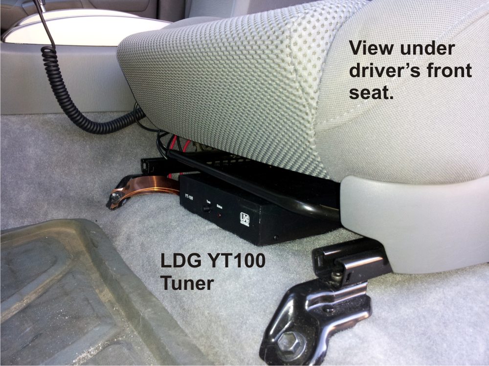
HF Antenna Tuner: I suspected that the shortened and coil-loaded HF antennas would exhibit a 2:1 (or lower) SWR bandwidth that was quite narrow, or high Q. (See the Ham Radio 101 article on Q-Factor.) I had purchased an LDG YT-100 automatic antenna tuner along with my Yaesu FT-857D, so I put it to use in the mobile installation. Especially on the very short, highly loaded 40-meter antenna, it was unlikely that I would obtain acceptable SWR values across the entire phone sub-band that I desired, so the tuner would come in handy to help mitigate the negative effects of high SWR when I ventured to the outer edges of the band.
I used a short segment of RG-8X to connect the tuner to the HF side of the transceiver, and I positioned the tuner so that its one-touch tuning button is front and center under the driver’s seat. When a manually initiated tuning cycle is required I just reach down and click the button without having to take my eyes off the road.
Especially with physically shortened ‘loaded antennas’ typically used in HF mobile installations, an antenna tuner will be quite useful, so plan for its inclusion in the cab near the transceiver chassis.
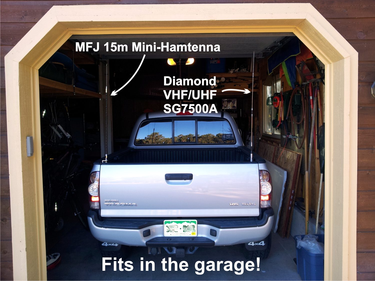
Once I began to use an antenna analyzer to evaluate the SWR functions of my HF antenna system with the variety of Hamtennas, I was pleasantly surprised by the breadth of the SWR bandwidth I was obtaining! I was particularly surprised by the values presented by half-pint-sized versions of the MFJ Hamtenna, called Hamtenna Minis, that I expected to have extremely narrow SWR bandwidth. The mini version antennas are only about 36 inches high and are heavily coil loaded for a single band like their longer siblings. And while such a highly loaded, very short antenna is going to impose some significant signal loss, the mini versions do fit into the garage! Remember, every antenna is a compromise, in this case a very convenient antenna with reduced performance. But…
Operational Results: The VHF/UHF functions of the mobile station worked beautifully. The dual band Diamond antenna and 5 to 15 watts of power are more than sufficient to hit loads of local repeaters that I use, as well as more distant machines on mountaintops 20 to 50 miles distant. Having installed multiple VHF/UHF stations in the past, I was more interested in the HF operational results.
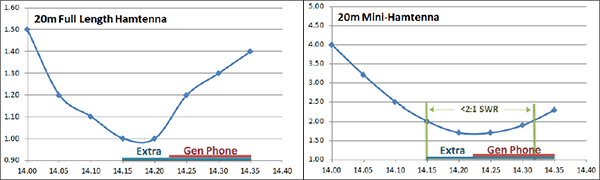
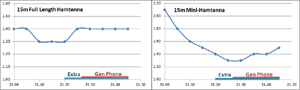
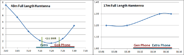
HF Results: The SWR curves obtained are presented at the end of this article by HF band, with the General Class and Extra Class phone portions of each band indicated along the frequency axis. As expected, the tuner helps with the 40-meter antenna to work across the full phone band, but it’s unnecessary with the full length 15, 17, and 20-meter sticks.
In my first HF contact attempt I used the 15-meter Hamtenna and contacted a station in south Florida from my Colorado home with a 5-9 signal report. That was encouraging! Similarly, my 17-meter band efforts were rewarded with nice signal reports from east coast to west. However, my 40-meter and 20-meter band efforts revealed some problems that I’ll describe below. First, an examination of those mini-stick antennas.
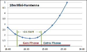
Mini-Antenna Results: The SWR curves with the mini-antennas are shown below also. I have not attempted the mini-40m antenna, but the 10m, 15m, and 20m versions are quite satisfactory in SWR bandwidth, with the tuner helping with the upper portion of the broad 10m band and upper 20m band. As to performance, I’m sure that some signal loss occurs as compared to the longer antennas, but I have still made some impressive contacts with these short little sticks and the 100 watts barefoot available from my FT-857D.
In the first few weeks of operations I’ve reached coast-to-coast with the short 20m and 15m antennas, and under good conditions reached into Europe and to St. Petersburg, Russia. With the short 15m antenna I contacted David DD8SM in Germany under less than ideal conditions, and with the mini-10m antenna the same day I had a QSO with Tom ON4DVD in Belgium. In somewhat better conditions I’ve made 15m contacts to Japan during the late afternoon hours.
Are these shortened HF antenna options providing the best performance available with a mobile rig? No, of course not. But they are getting out quite well and I have many enjoyable casual QSOs with them while driving to work or just on a quick errand across town. I’ve repeatedly received complements on the “great signal from the mobile rig!” And, it is clearly feasible to make DX contacts with barefoot power levels and antennas that fit into your garage!
A Little Trouble: That’s the final outcome story, but these quite satisfactory results did not come without a little troubleshooting and modification along the way. It is quite typical to experience a few problems, especially with an HF mobile installation, and rectifying various problems sometimes requires a shotgun approach of trial and error. You’ll need some patience and a little reasoning sometimes to pin down the source of a problem and eradicate it. I experienced some troubles immediately on 40-meters and on 20-meters, as follows:
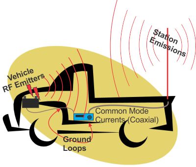
My first 40-meter contact was to a station in Texas about dusk one evening. The kind operator on the other end was able to understand my audio, but he digitally recorded it and re-transmitted it back to me to hear. The audio was somewhat garbled and slightly distorted with the signature signs of undesired RF on the signal – my own transmitted RF signal was getting picked up by my transmitter chassis and/or coaxial cable shield and/or my microphone cable and fed back into the transmitter. I’d have to track down this “common mode” RF problem and figure out how to correct it or 40-meter band operations were not going to be an option.
Further, while my 20-meter band signals were getting out well and were cleaner, they, too, were described as having slight “RF on the signal” problems. And that wasn’t all. My receiver audio on most bands was riddled with popping, cracking, ignition noise anytime my truck’s engine was running. On the 20-meter band it was particularly bad, masking many signals. That noise absolutely had to go!
You will likely run into a few problems, and a trial-and-error approach based in a little reasoning will usually solve them; realize that you may have to try a variety of solutions before you find the magic bullet(s).
I’ll further describe these problems and others, and the solutions to attack them, in part 2 of this mobile installation article in a few weeks. For now, start planning your mobile installation even if you think it may be months, a year, or more before you attempt it. The sooner you begin to scheme on an installation plan the sooner you’ll bring it to fruition! Good luck, and 73!
Stu WØSTU
Going Mobile, Part 2 (article continued)
Video of this mobile station in operation during CQ Worldwide DX Contest, Oct 2014
SWR Curves