Ham Radio Mobile Installation — Going Mobile (Part 1)
When I’m driving free, the world’s my home
When I’m mobile
Hee hoo!
Beep beep!
– Pete Townshend, The Who, Goin’ Mobile
Going mobile. Yeah, that’s a great idea! Installing a ham radio mobile station in an automobile is often the next step for many hams following the establishment of a home station or perhaps as the upgrade from an HT. A ham radio mobile installation greatly expands the utility of amateur radio and increases the opportunity of time to get on the air. [Video of this mobile station in operation during CQ Worldwide DX Contest, Oct 2014.]
A ham radio mobile installation also presents some unique and sometimes vexing challenges for the operator to overcome. Just consider it yet another opportunity to learn and to expand your growing ham knowledge!
There are many different feasible ham radio mobile equipment combinations and installation approaches that can result in a well performing mobile station in your vehicle. But no matter your individual selection of transceivers, antennas, mounting methods, coaxial cable routing, operating bands, and other factors, some common tenets of mobile installations apply and help to avoid or reduce problems that are inherent in the mobile environment. In this article I’ll describe just one installation example, but I will introduce some of the universal tenets that can help you succeed with your own mobile station.
The initial goals for the example ham radio mobile installation in my Toyota Tacoma truck that I’ll describe were:
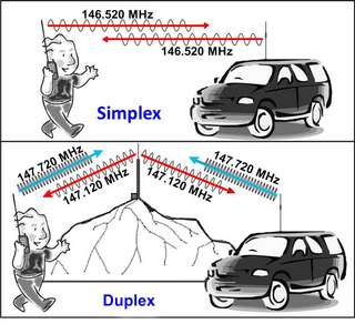
VHF/UHF FM phone for repeater and simplex operations on 2m and 70cm bands.
HF SSB phone for the higher HF bands of 10m to 20m, and also 40m.
Low cost (a relative thing, admittedly).
Low clutter and clean profile in the passenger cab.
Simplicity and ruggedness.
Minimal permanent impact or scarring of my precious new (used) truck!
Ease of portability – removal of the transceiver for use in portable ops (mountain-topping and contesting).
Garage parking, if only with antenna discombobulation.
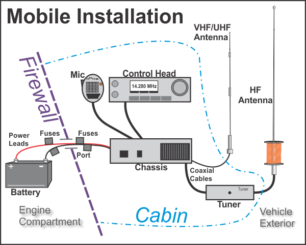
Much like antennas, every ham radio mobile station is a compromise, but I came close enough to achieving the goals above to be happy. Let’s start our look at mobile installing with a generic big picture block diagram of a mobile station.

The transceiver(s) and related components such as an antenna tuner usually reside within the passenger cabin. A ham radio mobile transceiver may be a single contiguous unit or it may have a detachable control head, allowing the bulk of the radio chassis to reside out of sight, perhaps under a seat or in a stowage compartment. The power leads will be routed through the firewall into the engine compartment to the car battery, while coaxial cable will be routed out to the antenna attachment locations on the exterior of the vehicle. A mobile station installation will require careful planning and component selection to ensure a well-integrated system that suits your needs and meets your mobile operating goals.
Let’s consider the various station components depicted in the block diagram and cover some installation fundamentals, tips, and recommendations for each.
The Transceiver: Besides your budget, your selection of a transceiver will be driven in large part by the bands on which you wish to operate. While variations exist, mobile transceivers tend to follow one of three primary styles:
VHF and/or UHF, FM mode only (and frequently accommodation for digital packet)
HF SSB mode (usually 10m to 160m bands, often with 6m VHF; also may have CW, AM, digital modes)
“All mode, all band,” which usually means something like 70cm UHF, 2m and 6m VHF, and 10m to 160m HF, including FM, AM, SSB, and CW modes, and accommodation for digital ops.
Most hams like to have VHF and/or UHF FM capability on the road in order to use local area repeaters and simplex communications. With that assumption, the decision then turns to whether or not you want to have HF mobile, too. If you do want to reach out to greater distances with single sideband using the ionospheric skip provided by HF, the decision tree then branches to one of these two common transceiver arrangements:
The all mode, all band transceiver, or
Two separate transceivers, one for VHF/UHF FM and one for HF SSB.
Decide whether you want HF in addition to VHF and/or UHF. If you do, select an ‘all mode, all band,’ transceiver or separate transceivers.
My choice was a compact all band, all mode transceiver from Yaesu, the FT-857D. It supported several of my mobile station goals nicely:
The unit is reasonably priced for the capabilities and performance it offers.
It provides 2m and 70cm for FM phone, along with 6m and the HF bands for SSB phone.
It offers a detachable control head to help reduce the visible clutter and footprint in the cab.
A single transceiver instead of two separate units keeps things a bit simpler.
I mounted the control head on a 6” ball joint arm with a clip mount and having stiff friction to support the load. The strong but small clip latched onto the left side of the console tray in the cabin, arcing the ball joint arm up and to the right so that the control head resides above the center of the console just in front of my gear shift handle and below the environmental controls of the dashboard. The ball joint arm came with a variety of snap on connector options opposite the spring-loaded clip end, and I used a little garage engineering to fabricate a mount for the control head that would easily attach to one of the snap-on connectors with its supplied friction nut.
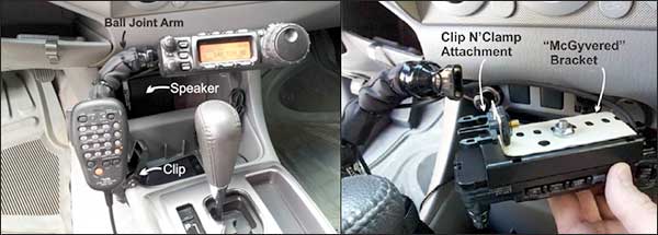
I tightly zip tied the microphone clip that came with the FT-857D onto the ball joint arm and it holds fast just above and right of my knee while driving. Overall, this arrangement helps satisfy my “ease of portability” requirement as well as the “minimal permanent impact” requirement. The control head readily discombobulates from the mount with the severing of a couple of easily replaced zip ties that reign in the connection cable, and the ball joint clamp provides a sufficiently stable mount without drilling, sawing, or mangling anything! (Yes, it sways a tiny bit when I hit a big bump, but it doesn’t droop or slip!)
With the ball joint clamp, the neatly zip tied cables, and the tidy microphone clip, the radio controls are easy to reach while driving, and the shift handle provides a perfect hand rest while dialing through frequencies. The microphone is out of the way but within easy reach without even a glance, right next to my knee. And the chassis of the FT-857D is hidden away under the driver’s seat with the various cables zip tied and tucked away beneath carpets and panels. Low clutter and a clean profile!
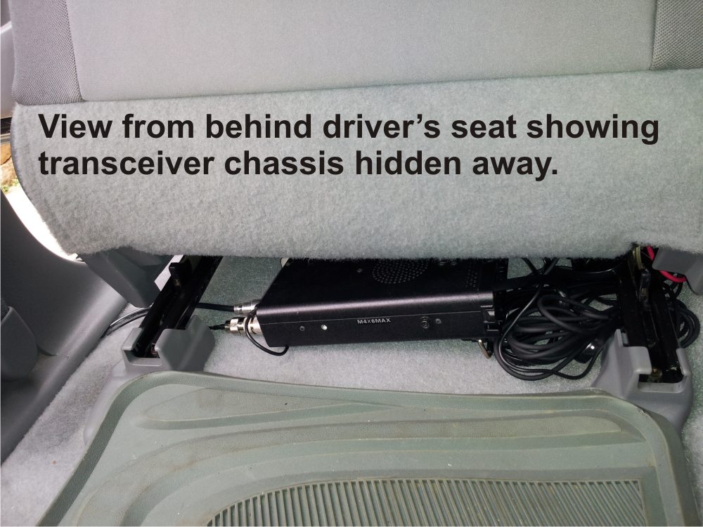
Because the FT-857D integrated speaker resides in the chassis stowed under the seat, I included an external speaker that rests nicely in one of the forward console compartment bays. I used an MFJ 281 Clear Tone speaker for its compact size and low price, and it sits nicely in the compartment facing the cabin to provide clear, loud audio. My ears are pretty bad, but with this little addition even I can hear a low-talking, under-driving ham’s transmissions.
When using a separated control head and a ‘hidden’ transceiver chassis, you may need to plan for an external speaker in the vehicle cabin.
Power Leads: The power leads for your ham radio mobile transceiver will usually be a set of wires that are sold with your radio. This will usually be a minimum AWG 14 gauge wire pair (often larger 12 or 10 gauge), with in-line fuses. If you are brewing your own power leads be sure to use heavy gauge wire with fuses appropriate to the maximum currents your transmitter will draw. A 100 watt transmitter coupled with 12 AWG wire and 25 amp fuses in both leads is a safe option. Generally, position a pair of fuses close to the battery connection. Many commercially provided leads sold with radios will have fuses closer to the transceiver, so adding a second pair under the hood is a good safety implementation.
Use in-line fuses on both power lead wires to reduce the possibility of fire or damage in the case of a short or other fault in the radio.
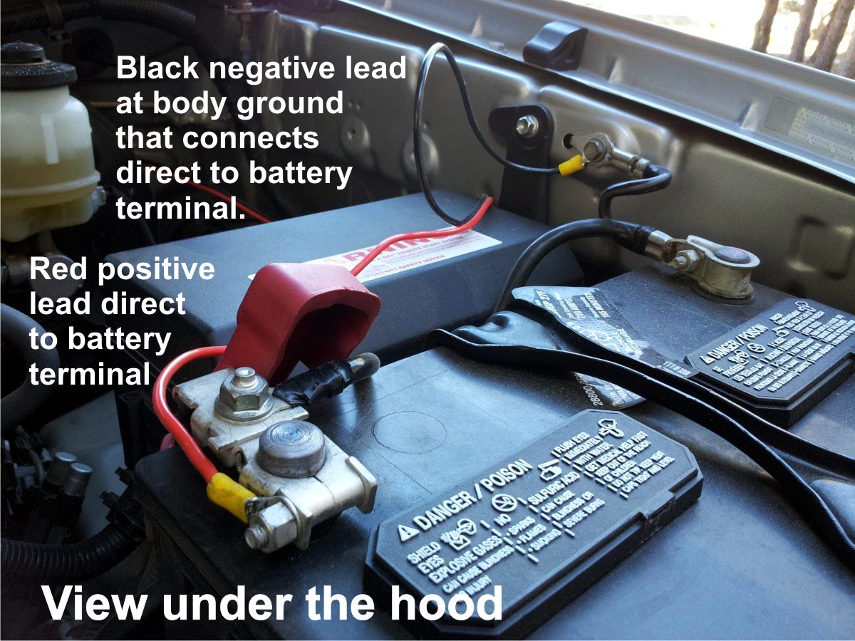
Important Note! Run your transceiver power leads directly to your vehicle battery terminals and avoid any use of existing automobile wiring. The wiring used in most car power outlets is not designed to carry the high currents that a transmitter may draw, and they may quickly overheat and start a fire. More likely you will just pop a fuse or two in your car’s fuse bank, but don’t risk it. Further, you may pick up all sorts of electrical noise if you try to use your car’s wiring. Just say no to automobile wiring!
Power leads should be routed directly to vehicle battery terminals, avoiding any use of existing automobile wiring.
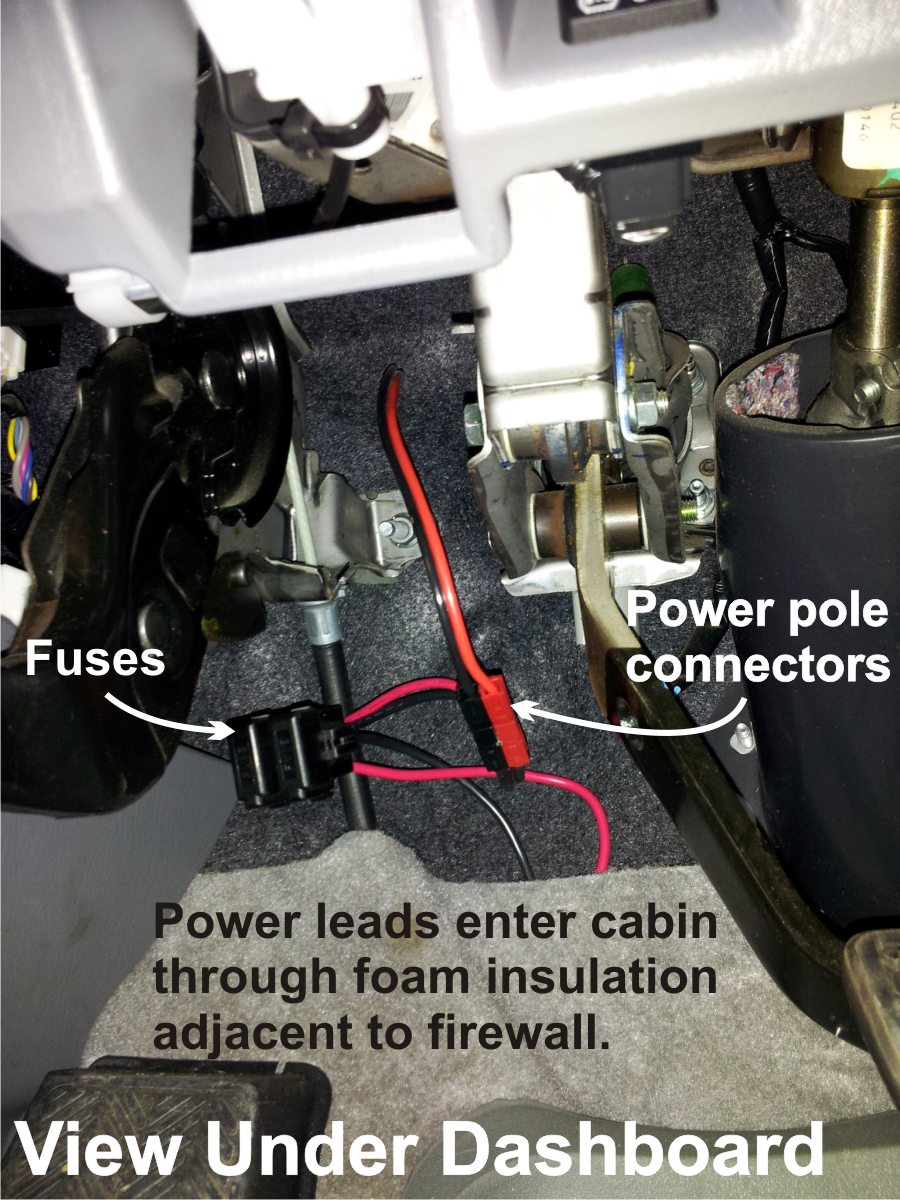
You’ll need to route the power leads through your vehicle’s firewall into the engine compartment to the battery. This can be a little tricky with some older vehicles and might require some drilling. Most modern automobiles have pre-existing access ports through the firewall and into the passenger cabin. These will almost always be plugged with a removable rubber “stopper” or grommet, and they are not always in the most convenient locations under the hood or under the dashboard. You may have to do a little searching, perhaps behind engine components and under carpet or trim, to discover that unimpeded path for your power leads.
Important Note! When routing power leads through a firewall port to the engine compartment, be sure to use a grommet or other heavy insulation around the wires. If you do not, the wires can chafe over time as they jiggle or rub on the metal edge of the port. Eventually this will lead to an electrical short to the car body when conductors are exposed, a potentially dangerous situation. It is often feasible to use the port’s rubber stopper or grommet with a little piercing or trimming to provide a good insulated pad between your power leads and the firewall hole’s edges.
Use a grommet in the firewall port to protect against chafing and electrical shorts over time.
In my truck installation I used the power leads and fuses supplied with the Yaesu FT-857D. Behind the master cylinder in the engine compartment I found an existing firewall port through to a position underneath insulation and trim inside the cab, high behind the dashboard. Routing the leads took a little time and effort, and I was able to use the port’s rubber plug, with its center carefully sliced out, as a grommet. The port position promoted concealment of the power leads behind the dash and under carpet and trim pieces all the way to the transceiver chassis under my seat.
Antennas: With the power leads routed from battery to transceiver, my attention turned to the challenge of antennas. I planned to use a dual-band 2m/70cm antenna at one mounting position and a separate mounting position for the HF band antenna(s). Several factors fed into the antenna selections and mounting positions. Keeping in mind the tenet that every antenna is a compromise, I selected antennas and mounting locations that were a compromise between convenience, cost, and performance.
Typically, at least two separate antennas will be required, one for VHF/UHF bands and one for HF bands.
VHF/UHF Antenna: With any antenna a higher mounting position is generally better for performance. A good rule of thumb to follow is to get as much metal mass under the antenna as possible, given other constraints. Another good tenet is that the antenna’s ground side (coaxial shield usually via the mount connection) should be solidly electrically connected to the vehicle metal mass, such as the frame and body. This will help provide a path for return currents to the antenna and enhance its performance.
A higher antenna mounting position will usually provide better performance than a lower one, and more metal mass ‘under’ the antenna is better, with solid electrical continuity between the antenna ground side and the vehicle mass.
For ¼-wavelength vertical antennas, a good ground plane is essential to good performance. A quarter wave antenna mounted solidly to the vehicle roof is a great option, but I wished to avoid drilling into the roof for mounting or coaxial cable routing. Further, I already had a nice 2-m/70-cm dual-band antenna available that extended about 40 inches high: a ½-wavelength antenna for 2-meter band, and 5/8-wavelength for 70-centimeter band. Mounting it on the roof of the truck would also have made garage entry a non-starter, and I was determined to keep my new (used) truck in the garage.
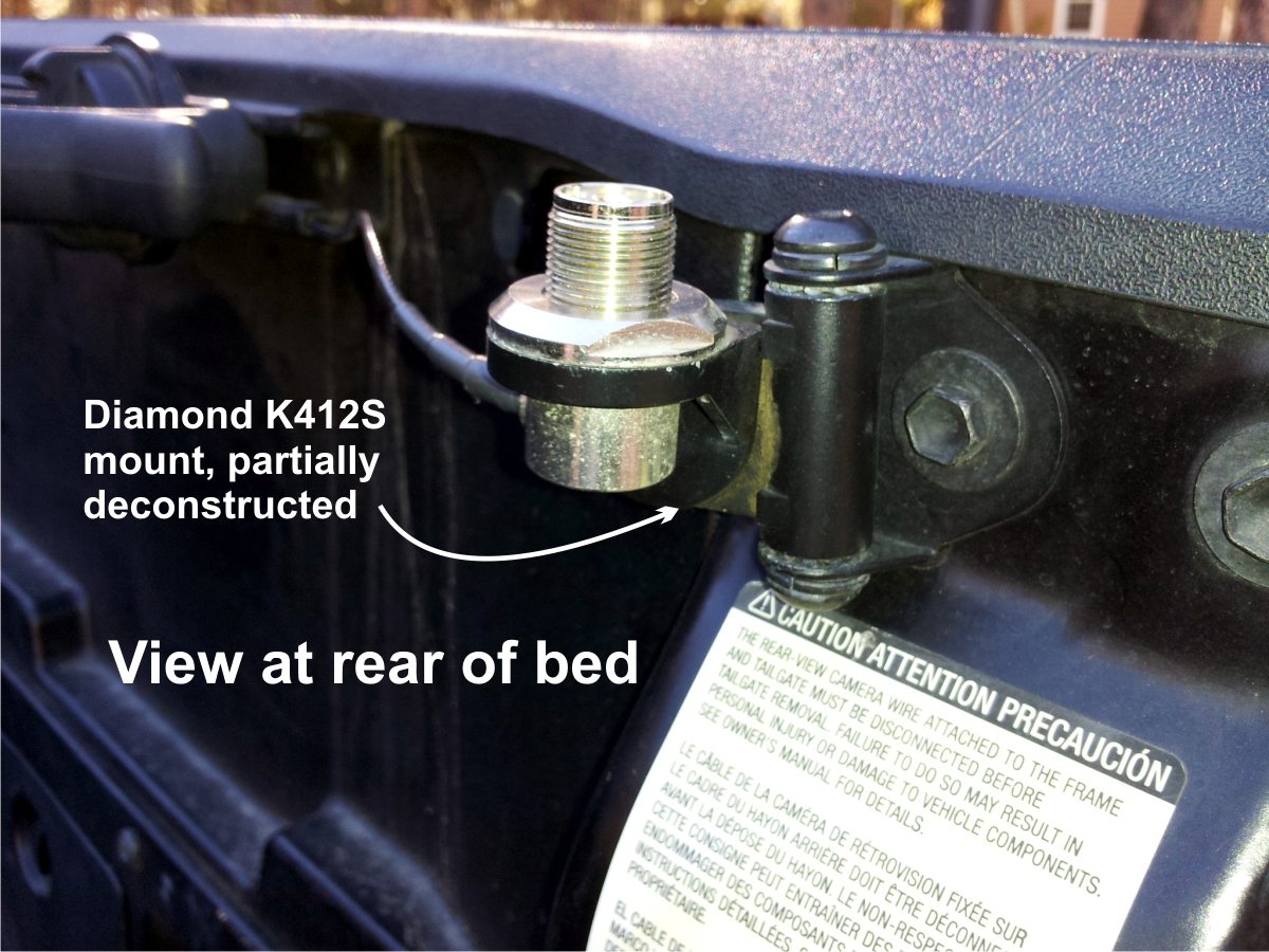
I found a pair of existing bolts at the inside top of the truck bed just inside the tailgate, passenger side, to which an antenna mounting bracket could be attached. The location near the rear of the bed kept the antenna clear of the rising cabin structure that could block signals, and it reduced the RF exposure to any passengers as compared to a front-bed or hood mounting position. Given that the truck was already quite high with a suspension lift package, mounting the UHF/VHF antenna at the top level of the truck bed wall kept it well elevated and, by absolute fortuity, extended it to about one inch below the opened garage door height. Perfect, and just lucky.
The Diamond SG7500A antenna had previously been mounted to another vehicle with a Diamond K412S lip mount. By detaching the curved clip portion that would normally snug onto the edge seam of a trunk or hatchback door, I was left with a single-hole antenna mount with a pivoting head for orienting the antenna. I was able to use one of the bolts near the top of the truck bed to secure the antenna mount. Contoured metal near the bolts helped prevent any pivoting or slipping of the mount once it was tightened securely with the single center bolt to the bed side. Voila! An elegant and unexpectedly simple solution for the VHF/UHF dual band antenna.
Of course, many other types of mounting schemes and products are available. I had some good luck in finding a simple solution that worked for my vehicle using on-hand resources, avoiding additional expenditures and promoting garage parking without antenna hassle… so far. This type of trunk and hatchback mount for lightweight VHF/UHF antennas usually works quite well and provides great flexibility in mounting locations along a car’s creases and contours. The Diamond K400 series trunk and hatchback mounts are very popular and well made, and they can even support lighter HF antennas with minimal or no scarring of the vehicle.
I’ll address the routing of coaxial cable for the VHF/UHF antenna along with that of the HF antenna in a moment, but first let’s consider that more difficult HF antenna and its mounting.
HF Antenna: Initially I considered a big-coil, adjustable load (or “screwdriver”) HF antenna that would use some fancy circuitry and mechanisms to cover multiple bands with ease once properly installed. But, after considering the price of those big babies, the heavy-duty mounting hardware typically required, and the extra complexity added by the controller, I chose otherwise. I wasn’t certain that mobile HF operation was something I would really get into, so I didn’t want to make such a big investment of time, effort, and money just to get a taste of it. Further, I like to take my truck on rough mountain roads in the Rockies, and I was concerned that such an antenna could be too delicate to get severely jostled around on a regular basis without taking damage.
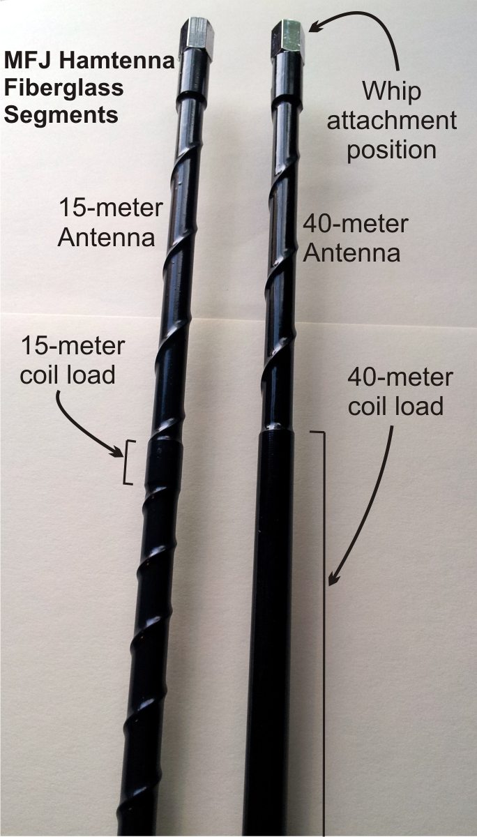
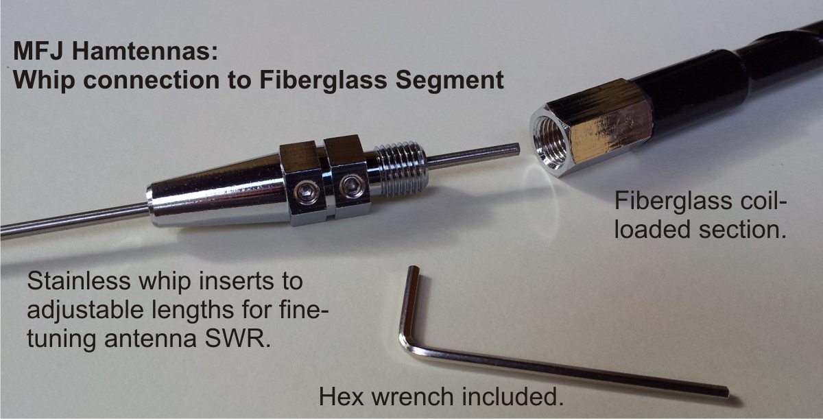
Instead I traded convenience for low cost, relative simplicity, and durability, consistent with my installation goals. I chose to use a simple and lighter antenna mount on which I could manually trade out single-band, coil-loaded vertical antennas commonly referred to as “ham sticks.” Specifically, I selected a set of the MFJ HF Sticks. These antennas use a standard 3/8” x 24 threaded mount, have a rugged fiberglass base segment, and employ an adjustable length stainless whip up top. The fiberglass section of each antenna has the loading coil seal-wrapped around it to the extent required for its particular HF band. The stainless whip inserts inside the fiberglass segment to variable lengths for adjusting the antenna resonance to the portion of the band desired. The whip segment is secured by set screws at the top of the fiberglass segment. Each MFJ Hamtenna I wanted costs under $30 and extends roughly 7 feet in total height. At that price, I don’t mind if I bend or break one on occasion, but they are very rugged.
Every antenna is a compromise, especially in a mobile station.
Mounting the HF Sticks (formerly known as "Hamtennas") on the top rear edge of the truck bed, directly across from the VHF/UHF dual band antenna, was an enticing idea. An identical set of two bolts resided on the driver’s side there, and it would keep the HF Stick high and distant from the cab. But before I settled on that idea I checked the electrical continuity between those mounting bolts and the truck bed, body, and frame. There would not be much of a horizontal, flat ground plane underneath that location, so I wanted to make sure the electrical continuity would provide at least moderate ground connectivity for return currents.
Ham Radio Mobile Installation -- Going Mobile, Part 1 (continued...)